back to blog overview
Key Components in Test Bench Construction
April 29, 2025
Reading time: 4 min
When we think about new test methods or develop test arrangements for customers, in 99% of cases this is done in a proven pipeline, starting from the point of friction:


When we think about new test methods or develop test arrangements for customers, in 99% of cases this is done in a proven pipeline, starting from the friction point:
First you consider which geometries are in contact in the real system, which relative movements they exert on each other, whether there are overlapping actuators, which media could separate the surfaces and where there is tightness and looseness in the system. You investigate which forms of movement and acceleration can be found in the real system and where the limits of the load collective are.
Once you have done this, you have a small tribological system cube and can think about the input and output variables.
Input variables – what type of actuator brings the movement into play, what performance data does it have, is the system influenced by a certain atmosphere and what loads does it work against, i.e. what are my normal force vectors and what methods of load application are possible?
Output variables – how do friction and wear presumably manifest themselves in the system, which sensor technology is expedient for the best possible description of my system? How close do I have to get to my tribological system cube in order to obtain any meaningful information from the system and what losses can I expect?
So you add the actuator and sensor cube to the tribosystem cube and, if necessary, you fit it all into the test bench cube (atmosphere chamber if required, of course).
From a purely scientific point of view, most of the work has already been done, the tribosystem understood, actuators and sensors optimized, publication actually already written. From the test bench builder’s point of view, the difficulty now begins – how can I bring these elements together without my test becoming too compromised? If I need too many bearings to decouple my rotating system, I will end up measuring more support bearings than test bearings. If I have to encapsulate my tribological system cube, my temperature measurement may be too far away from the friction point and I lose too much important system information. So the search is on for a link.
With enough experience, you eventually know the standard systems well enough that you have developed go-to solutions or at least approaches for many things that can be easily transferred.
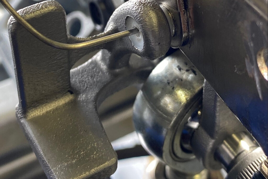
Not so for a hinge test for which we developed a test stand some time ago. Here it was clear how the system would work – a normal force-loaded rotating rivet, a clearly defined swivel movement. We knew that wear would be expected in the test, that frictional heat would be generated and that ideally we would want to trace the frictional torque back to the adjustment angle. It was clear that there would be no standard part that would meet all the requirements, so we set out with the 3D printer in our luggage to test geometries until we came close to the special shackle and were able to solve all our problems with it. The special shackle not only holds our tribological system, it is also the point of application for our normal force and temperature measurement. Clearly defined surfaces also enable optical path measurements for the swivel angle and wear measurement. Without this, testing would not exist in the form it does today – a good example of how individual components can be decisive in mechanical engineering.
On the subject of production – we ultimately decided to SLM print our shackle. A traditionally manufactured version would also have been possible, both have advantages and disadvantages:
The traditionally manufactured variant has several parts and introduces variance and error potential into the test series due to the installation and removal of each test. The printed version has to be elaborately reworked after production in order to meet the high accuracy requirements at the end. But it is a part that simply works.
In terms of cost, the two are ultimately the same for a quantity of 1, but a clear advantage of 3D printing is that you can design components exactly as you need them without spending too much time on feasibility – you can get creative and find the key component for your test bench more easily.